
A Camera Is Not a GPS Receiver: How Visual-Inertial Odometry Helps Drones Navigate
A drone can have a perfectly good camera feed and still have very little idea of where it is.
This becomes a problem when GNSS signals are unavailable or unreliable. Indoor environments, covered structures and areas with difficult signal conditions can make satellite-based positioning less useful. Yet the aircraft still needs an estimate of its movement to maintain controlled flight.
One approach is Visual-Inertial Odometry, usually shortened to VIO.
It combines information from cameras and inertial sensors to estimate how a vehicle is moving relative to a local starting point. The interesting part is not simply that a drone can see its surroundings. It is how two very different types of sensors compensate for each other's weaknesses.
What the camera knows — and what it doesn't
A camera records images, not geographical coordinates.
Visual odometry works by identifying visual features in successive frames and observing how their apparent positions change. From those changes, an algorithm estimates the camera's movement through the environment.
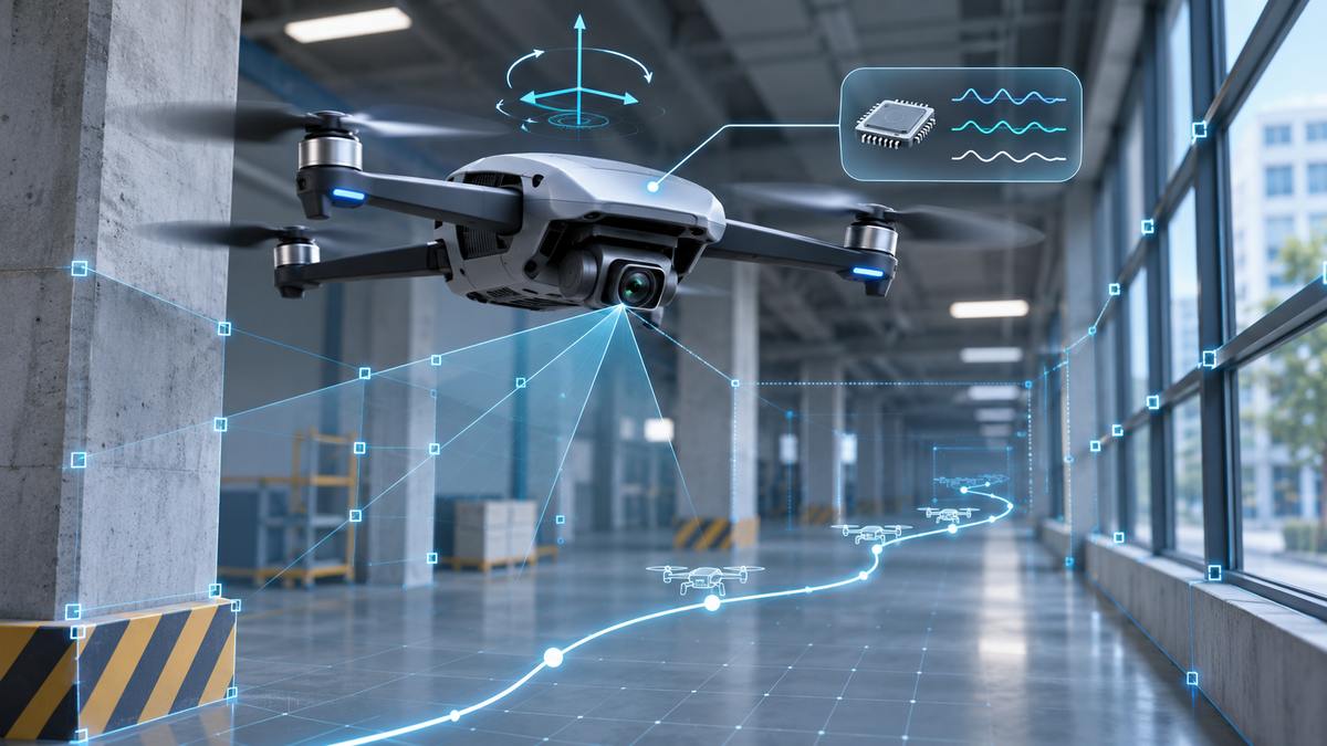
Imagine a drone moving past a wall with visible patterns, corners and other recognizable details. The camera captures these features repeatedly. By comparing frames, the system can estimate how the camera has moved.
But vision alone has limitations.
Rapid motion can produce blurred images. A surface with very little visual detail offers few useful features to track. Changes in lighting can also make reliable tracking more difficult.
A camera provides valuable information, but it does not provide a complete navigation solution on its own.
Why an IMU changes the picture
An Inertial Measurement Unit (IMU) typically contains accelerometers and gyroscopes.
The accelerometer measures specific force, while the gyroscope measures angular velocity. These measurements describe how the aircraft moves and rotates over time.
An IMU responds much faster than a typical camera frame sequence, making it useful when the aircraft moves quickly between images.
VIO combines the two information streams:
- The camera provides visual observations of the surrounding environment.
- The IMU provides rapid measurements of motion and rotation.
- The estimation algorithm combines these observations to calculate a more useful movement estimate.
The result is an estimate of position, orientation and velocity relative to a local reference, rather than an absolute geographical position.
That distinction matters. VIO does not automatically tell the drone its latitude and longitude.
VIO is not the same as optical flow
These terms are sometimes used interchangeably in casual discussions, but they describe different capabilities.
Optical flow systems commonly use a downward-facing camera together with a distance sensor to estimate two-dimensional velocity.
VIO goes further by combining visual information with IMU measurements to estimate three-dimensional pose and velocity.
The distinction is important when discussing navigation architectures. A system designed to maintain position over a nearby surface is not necessarily capable of providing the same information as a full visual-inertial navigation system.
PX4 documents both approaches as separate computer-vision capabilities.
The difficult part is often integration
Running a VIO algorithm is only one part of building a working aircraft.
Consider a typical PX4-based architecture:
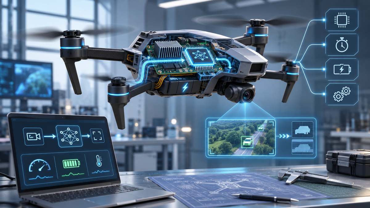
A camera supplies images to a companion computer. A visual-inertial estimation process runs on that computer, often within a ROS-based software environment. The resulting odometry information is then sent to the flight controller through an appropriate interface.
PX4 can use external vision information through its EKF2 estimator.
Several details can determine whether this arrangement works reliably.
Camera mounting and vibration: A camera that moves or vibrates relative to the aircraft frame introduces errors. PX4 specifically recommends vibration isolation for sensitive tracking cameras.
Timing: Camera measurements and IMU measurements must be aligned in time. A delayed position estimate can be misleading even when the underlying algorithm is functioning correctly.
Coordinate frames: The camera's orientation relative to the aircraft must be represented correctly. A mismatch can produce unexpected movement estimates.
Estimator configuration: External vision measurements need to be configured and fused appropriately. Sending valid messages does not automatically guarantee a reliable navigation solution.
These are engineering problems, not merely software installation problems.
Where VIO reaches its limits
VIO is useful, but it is not a universal replacement for GNSS.
Visual tracking can deteriorate in environments with insufficient visual features. Vibration, motion blur, poor image conditions and calibration errors can all affect the estimate.
There is also a longer-term issue: errors in estimated movement can accumulate into position drift.
More advanced visual-inertial SLAM systems introduce mapping and loop-closure techniques to help recognize previously observed locations and correct accumulated errors. However, those capabilities should not be confused with what every basic VIO implementation provides.
The practical question is therefore not whether a camera can replace GPS.
It is how different positioning sources can be combined, monitored and used within the limits of the aircraft's actual environment.
A drone that understands the limitations of its sensors is more interesting, from an engineering perspective, than one that simply claims to be autonomous.
Further reading
- PX4: Visual Inertial Odometry
- PX4: Computer Vision
- ORB-SLAM3: An Accurate Open-Source Library for Visual, Visual-Inertial, and Multimap SLAM
This article is a technical overview based on published research and engineering documentation. It does not describe a particular aircraft test or independently verified flight experiment.
About the author
- An independent editorial team exploring drone engineering, artificial intelligence, robotics, autonomous flight and the technologies shaping the future of unmanned aviation.
Comments
Join the discussionThe coordinate-frame check should include uncertainty as well as position and orientation. Rotating a pose into the aircraft frame while leaving an anisotropic covariance in the camera frame changes which direction the estimator believes is reliable, even when the pose message looks plausible.
A replay fixture with a known mounting rotation and much greater uncertainty along one camera axis would make this visible. The transformed pose and uncertainty should agree about the same physical direction. That would test a part of the integration contract that a straight-line trajectory with symmetric uncertainty can accidentally hide.